Digital-to-Analog Speedometer Swap 1981-1985
Link to: Eldorado Speedometer History
Link to: Tech Refs including Wiring Diagrams
Return to: Main Page
|
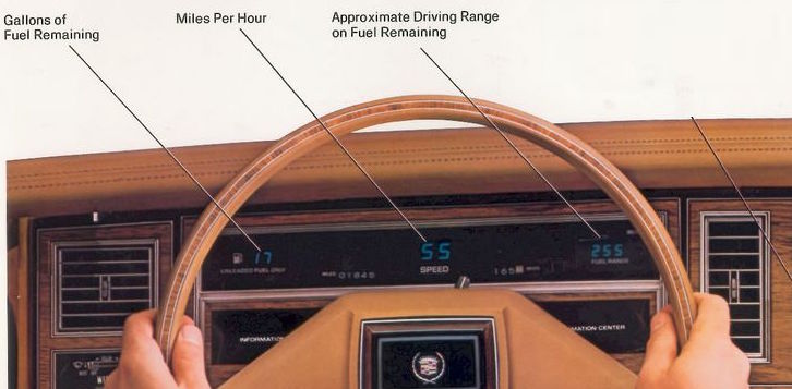
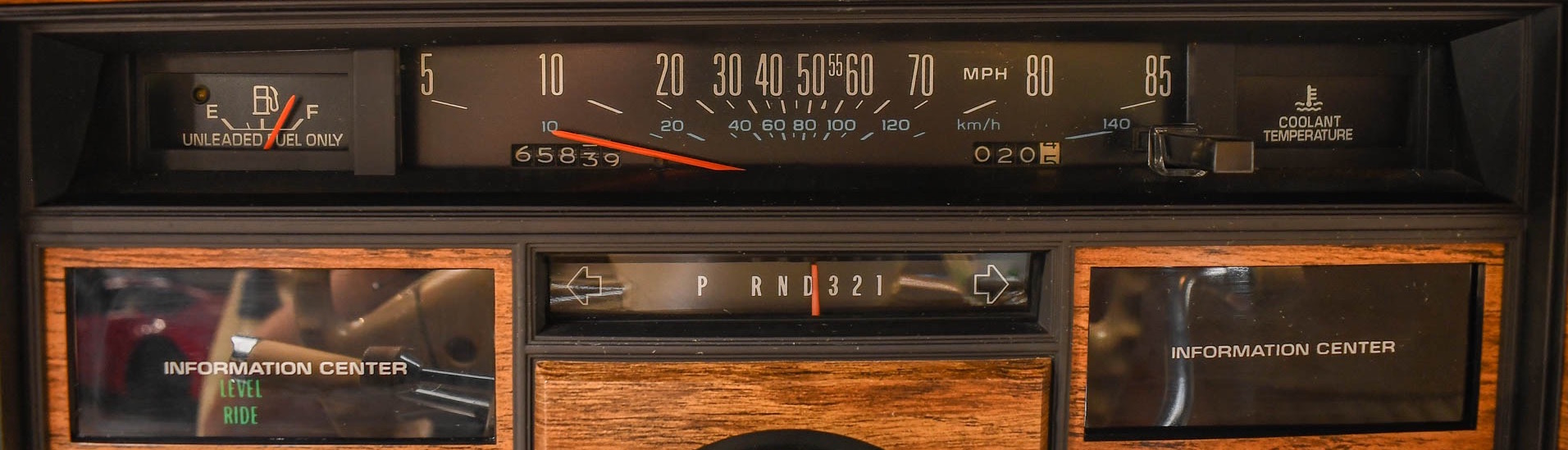
Let's face it, the factory digital speedometer leaves a little something to be desired. Not only do you lose that ever-important 'Coolant Temp' light that the analog cluster puts right in your line of sight, but you pick up quite a bit of flat black plastic in an otherwise nicely appointed interior. To make things worse, a lot of these Eldos and Sevilles had the options heaped onto them, so the analog cluster, in my experience, can be harder to find in the wild. If the digital display is more your thing, more power to you! But for those that would prefer to swap in the analog, there are a couple of 'gotchas'.
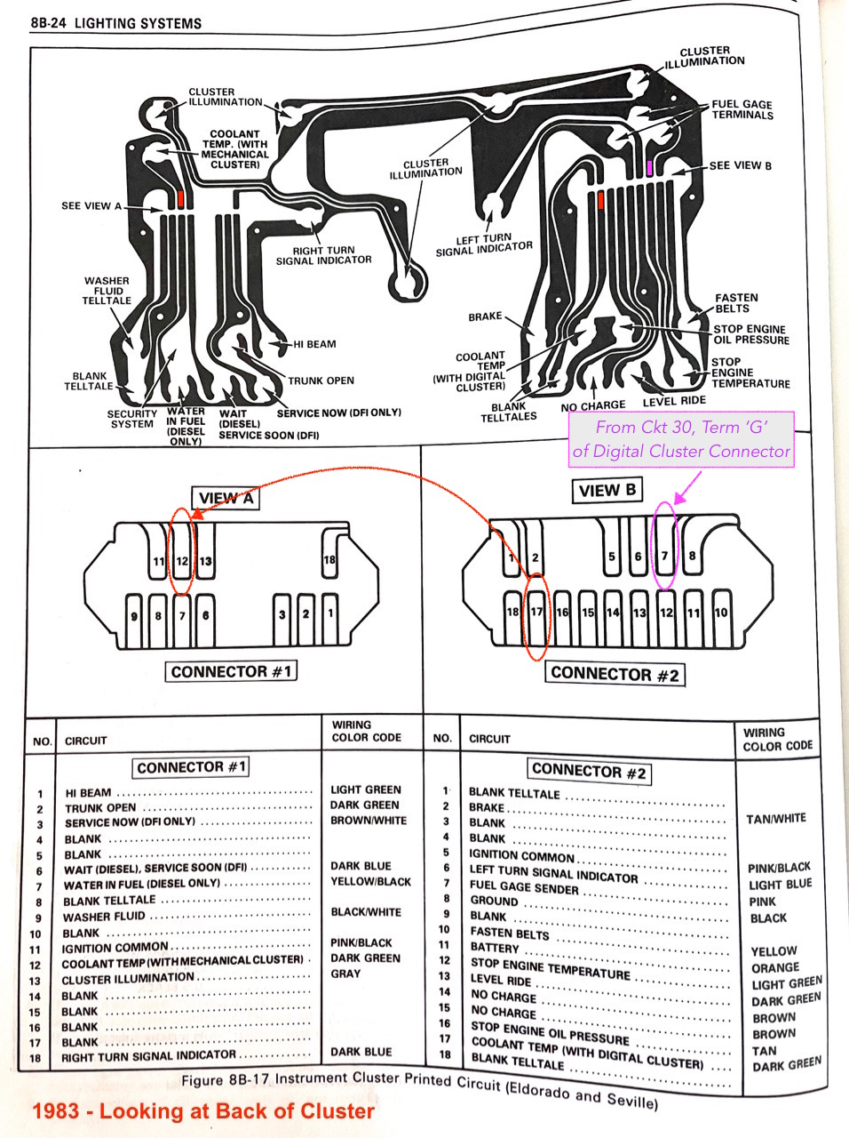
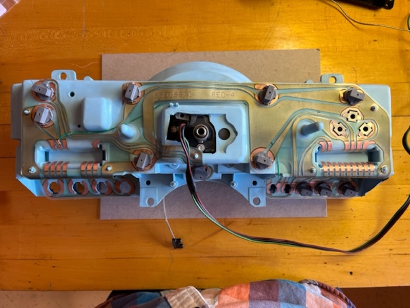
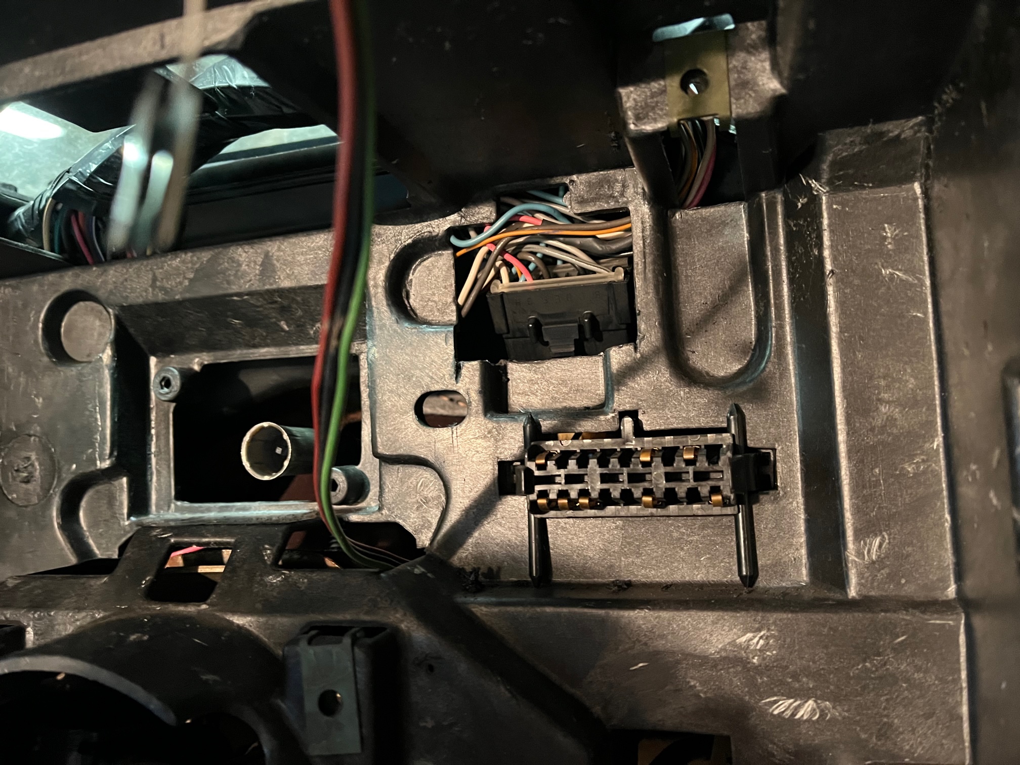
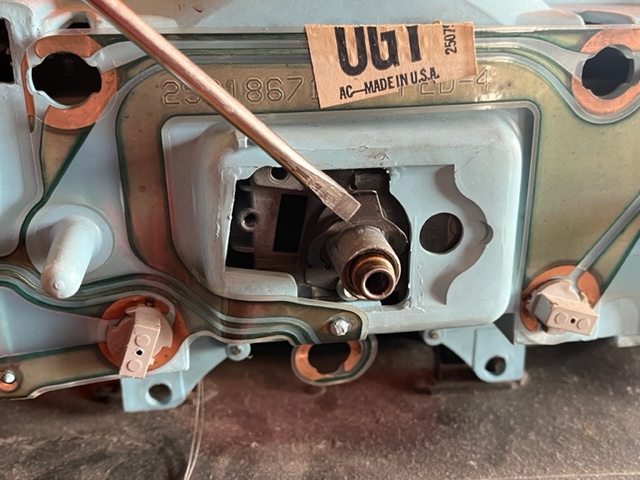
The good news? Both instrument clusters use a physical speedometer cable, and both plug right into the dashboard backshell. Both have mechanical barrel odometers and of course, the same mounting points. The biggest difference is that the digital cluster makes use of a 3rd connector which communicates with the ECM. While this isn't needed for the analog cluster, it does carry the fuel level circuit you'll need for the analog dash. (see image below) In addition, all warning lights should work after the swap except Coolant Temp. The digital dash puts it in the left Info Center panel. The analog puts it in a highly visible location to the right of the speedometer. One approach is to physically move the wire on the dash-side from the left connector to the right, however wire length may be an issue (the harness is tape-wrapped and very hard to get at without major dashboard surgery). The method I prefer is to simply tack-solder a jumper on the backside of the cluster from one bulb location to the other (see photo). Make sure you get on the 'signal' side of the bulb, and not the common side.
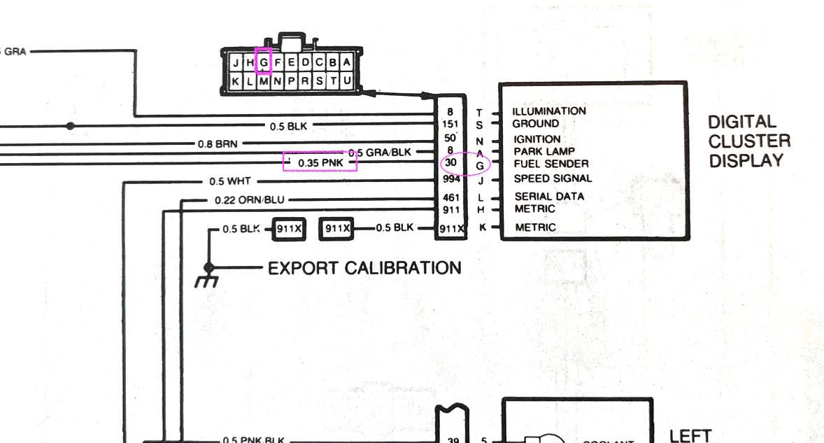
As for the fuel level, you need to get the signal from pink wire "G" in the digital cluster connector (above & below) to location 7 of the left-hand telltale connector. You could solder a flying lead off the back of the speedometer, clip the pink wire at the display connector, and mate the two with an insulated spade connector, but there is a cleaner way. I chose to grab a terminal w/wire from a parts car, snapped it into location 7 and ran it over to the pink wire (G) on the display connector. I didn't cut the pink wire, but rather tapped into it (soldered connection) so that both connectors now have fuel level, should I one day want to put the digital cluster back in. If you don't have a parts car to steal a terminal from, and you're doing an engine swap, re-purpose one of the 'no-longer-needed' ones, like Service Soon.
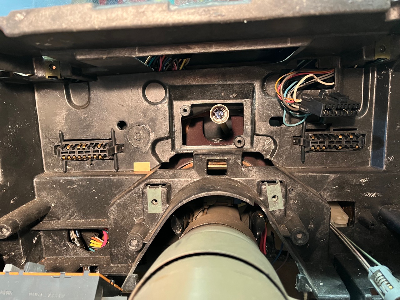
Easy enough, eh? There's just one more little problem. Without a place to plug that digital cluster display connector into, it's physically in the way of the analog cluster. And since the harness was installed to the back of the dash shell before the ducts were installed, you can't push it back through the opening. So you have three choices: 1. Remove the entire dashboard down to the firewall, disassemble it, then tuck the connector back inside, never to be used again. Nah. 2. Clip all of the wires off the connector and heat shrink the ends to prevent shorting. Defeats compatibility. Or the obvious choice...3. Grab the Dremel and open the hole up just enough to tuck the connector back inside. Done.
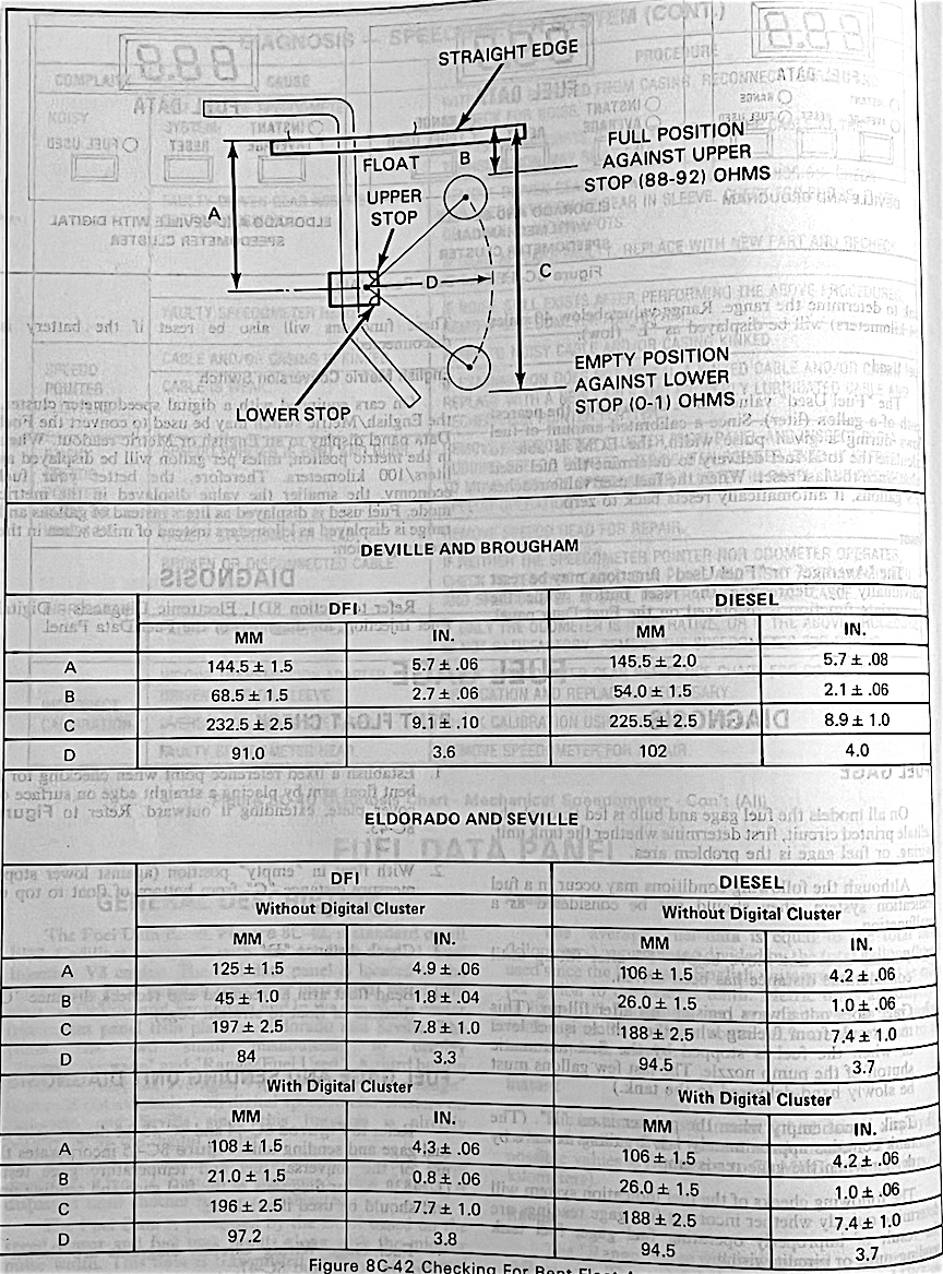
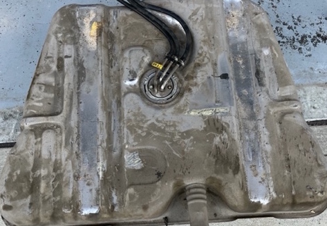
The above information assumes you're converting a 4100 Eldo (1982-85). A digital speedometer was offered in 1981, but the 'digital cluster' connector has a different pinout. Fuel Level is still on circuit 30 (pink wire), but the terminal is H rather than G. In the interest of full transparency, digital speedometer Eldos use a different part number fuel sending unit (p/n 25002276, identified by a yellow sticker). The manual doesn't elaborate on the purpose, but it does show that the float arm geometry is different (the tank is the same). I assume it improves linearity which would be required when you need to be accurate to +/- 1 gallon for the digital readout. In my experience, you DO NOT need to change a digital sending unit out for an analog conversion (p/n 25002511). Now, going from analog to digital would be another matter.
Comparing a '79 analog cluster to an '85, it looks like they should directly interchange. The only 'gotcha' is that the earlier clusters (79-81) don't have a clip on the speedometer cable, the cable is rigidly mounted to the dash shell and is not physically attached to the cluster. But, if you're creative, you should be able to move the clip over to accomplish the job. Also, be aware the early clusters have a 3-spd PRNDL, while '82 up is the 4 speed. The PRNDL indicator can be swapped. Warning lights should end up in the same locations, but if making electrical mods, you'll want to verify pin-outs first. If swapping engines, see the Electrical Swap Page for more details. |


|
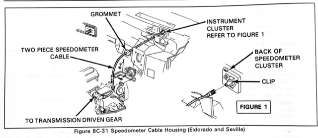
SPEEDOMETER CLUSTER INSTALLATION The later cars (I'm assuming with the trans update in '82) use two speedometer cables that mate adjacent to the brake booster. I imagine this was done to aid in assembly; the inner cable locks onto the speedometer and was probably installed during dash build-up. When the dash was mated to the body, the short cable could be easily passed through the firewall and connected later. On a '79 for example, it's one cable, but is rigidly attached to the dash housing so the speedometer can be removed without messing with a clip. The design of the dash shell and cluster is really such that the cluster is not intended to be removed/installed as an assembly once the dash is mated to the car. The shop manual would have you disassemble the cluster in-situ, and pull the speedometer head out, leaving the shell in place. That's a ton of screws, and a ton of risk. (The Toro is even worse). The reason being, you have to angle the cluster to get it to tuck up into the dash shell, but you can't angle it if the cable is attached. Attacking from above (with dashpad removed) allows you to unclip the cable. For reinstall, you have to attack from below. After you snake your speed sensor wire into the dash, set the cluster in such a way that it stays put, and lay on your back on the floor. Now tilt the cluster so the top 'tucks in' to the dash shell, and line up the cable. Using your other hand, reach up along the firewall above the brake pedal and grasp the cable, now push it towards the cluster as you hold the cluster with your other hand. You should have just enough vantage from below to see it's aligned before fully committing. The cable should slide just a little and 'lock' in place. If the dashpad is still off, you can inspect from above. Now reverse the removal instructions to complete the job. If this is part of an engine swap, you might want to wait to install the final trim bezel until you've also completed wiring up the Cruise Control. When you go to install the final woodgrain bezel, be extremely gentle with the philips head screws. Just snug them up or the plastic ears WILL crack.
|
|||
Return to Main Page Comments? Corrections? Contact Webmaster Cory Heisterkamp 2022