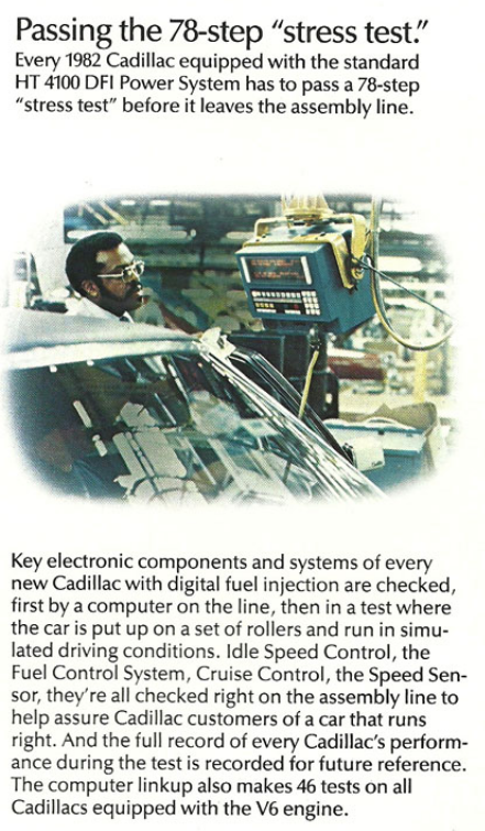
|
1980-1985 Cadillac DEFI Diagnostics Many years ago, I kept a cheat-sheet in the glovebox of my '85 Biarritz so that I could monitor RPM and digital speed on the climate head with a few key-presses. Years later, this information, once prevalent on the web, seems to have vanished. The below is copied from the now-defunct HT4100 chapter webpage of the CLC, originally taken from the Cad shop manuals, and applies to the 82-85 models. For the 80/81 cars, there are some differences. Unless otherwise noted, assume codes/parameters are the same. |
 |
|
|
To Enter Diagnostic Mode, Proceed as Follows: 1. Turn the ignition ON The engine control solenoids, some dash warning lights and the ISC can be tested using the Output Cycling capabilities of the system (see below). Switch Tests enable the testing of many of the switches in the car, including a comprehensive test of the Cruise Control controls. |
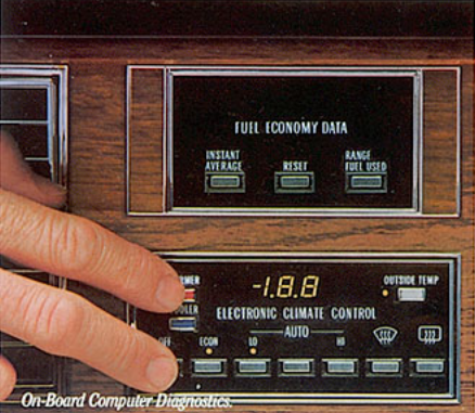 Casually reach around the steering column with your left hand, and using your two most inconvenient fingers, awkwardly press Off+Warmer as shown. |
|
CODE |
Circuit Affected |
CODE |
Circuit Affected |
| 12 | No Distributor (TACH) Signal | 44 | Lean Exhaust Signal (80 not used) |
| 13 | O2 Sensor Not Ready (80 not used) | 45 | Rich Exhaust Signal (80 not used) |
| 14 | Shorted Coolant Sensor Circuit | 51 | PROM Error Indicator (80 not used) |
| 15 | Open Coolant Sensor Circuit | 52 | ECM Memory Reset Indicator (80/81 not used) |
| 16 | Generator Volatage Out Of Range (80 not used) | 53 | Distributor Signal Interrupt (80/81 not used) |
| 18 | Open Crank Signal Circuit (80 not used) | 55 | 1980 Only - "ECM" |
| 19 | Shorted Fuel Pump Circuit (80 not used) | 60 | Transmission Not In Drive |
| 20 | Open Fuel Pump Circuit (80 not used) | 61 | Set/Coast/Resume/Accel Depressed Simultaneously |
| 21 | Shorted Throttle Position Sensor Circuit | 62 | Cruise Engaged while exceeding 80 MPH |
| 22 | Open Throttle Position Sensor Circuit | 63 | Car And Set Speed Tolerance Exceeded |
| 23 | EST/Bypass Circuit Problem | 64 | Car Acceleration Exceeds Maximum Limit (icy/wet pavement) |
| 24 | Speed Sensor Circuit Problem | 65 | Coolant Temperature Exceeds Maximum Limit (while cruise engaged) |
| 25 | 1981 only: Modulated Displacement Malfunction | 66 | Engine RPM Exceeds Maximum Limit (while cruise engaged) |
| 26 | Shorted Throttle Switch Circuit | 67 | Shorted Set Or Resume Circuit (81 not used) |
| 27 | Open Throttle Switch Circuit | 68 | 81: Set/Coast & Resume/Accel Improperly Set |
| 28 | Open Fourth Gear Circuit (80: see 30; not used for 81) | .7.0 | System Ready For Further Tests |
| 29 | Shorted Fourth Gear Circuit (80: see 30; not used for 81) | .7.1 | Cruise Control Brake Circuit Test (Brake Light Switch) |
| 30 | ISC Circuit Problem (codes 28, 29, 30 for '80) | .7.2 | Throttle Switch Circuit Test |
| 31 | Shorted MAP Sensor Circuit | .7.3 | Drive (ADL) Circuit Test |
| 32 | Open MAP Sensor Circuit | .7.4 | Reverse Lamp Sw. Circuit Test |
| 33 | MAP/BARO Sensor Correlation | .7.5 | Cruise On/Off Circuit Test (new for 81) |
| 34 | MAP Signal Too High (aka MAP Hose) | .7.6 | "Set/Coast" Circuit Test (new for 81) |
| 35 | Shorted BARO Sensor Circuit | .7.7 | "Resume/Accelleration" Circuit Test (new for 81) |
| 36 | Open BARO Sensor Circuit | .7.8 | "Instant/Average" Circuit Test |
| 37 | Shorted MAT Sensor Circuit | .7.9 | "Reset" Circuit Test |
| 38 | Open MAT Sensor Circuit | .8.0 | A/C Clutch Circuit Test (new for 81) |
| 39 | TCC Engagement Problem (80/81 not used) | -1.8.8 | Display Check |
| 40-43 | Not Used | .9.0 | System Ready To Display Engine Data |
| .9.5 | System Ready for Output Cycling Or In Fixed Spark Mode | ||
| .9.6 | Output Cycling | ||
| .0.0 | All Diagnostics Complete |
Live Data / Parameters (1981-85)
|
To enter Engine Data Display Mode, proceed as follows: 1. Turn the ignition ON. Tests can be performed with the motor off or running. Some data will be zero if the motor is off, eg RPM or if the car is not moving, eg Vehicle Speed. |
|
Parameter # |
Parameter |
Range |
Display Units |
|
.0.1 |
Throttle Position |
-10 to 90 |
Degrees |
|
.0.2 |
Manifold Air Pressure |
14 to 108 |
KiloPascals (kPa) |
|
.0.3 |
Barometric Air Pressure |
14 to 108 |
KiloPascals (kPa) |
|
.0.4 |
Coolant Temperature |
-40 to 151 |
Degrees Celsius |
|
.0.5 |
Manifold Air Temperature |
-40 to 151 |
Degrees Celsius |
|
.0.6 |
Injector Pulse Width |
0 to 19.9 |
Milliseconds |
|
.0.7 |
Oxygen Sensor |
0 to 1.99 |
Volts |
|
.0.8 |
Spark Advance |
0 to 52 |
Degrees |
|
.0.9 |
Ignition Cycles |
0 to 50 |
Key Cycles |
|
.1.0 |
Battery Voltage [81: open/closed loop ind where 1=closed] |
0 to 19.9 |
Volts |
|
.1.1 |
Engine RPM [81: Batt Voltage; will not display 10's digit] |
0 to 199 |
RPM/10 |
|
.1.2 |
Vehicle Speed [81: n/a] |
0 to 199 |
MPH |
|
.1.3 |
PROM I.D. [81: n/a] |
0 to 199 |
Code |
|
TLA |
Full Name |
Description |
Where positioned |
|
ECM |
Electronic Control Module |
The ECM is a digital computer which takes inputs from sensors around the engine bay and computes the ideal fuel/air mixture at that point in time. It also maintains the Cruise Control and other onboard systems. Sometimes referred to as an ECU. |
Aluminum-cased, the ECM is behind the lower right instrument panel cover. Also visible by removing the glovebox liner. |
|
TACH |
Distributor Tachometer Signal |
Pulses from the HEI distributor for RPM usage |
Rear center of the engine. |
|
O2 Sensor |
Oxygen Sensor |
Senses Oxygen level of exhaust |
Screwed into left hand exhaust manifold. If faulty, can cause mixture to be too rich or too lean. |
|
CTS |
Coolant Temperature Sensor |
Measures Engine Coolant Temperature |
Front left corner of Intake Manifold (4.1). A faulty sensor will cause extremely rich or lean running. |
|
MAT |
Manifold Air Temperature |
Measures Intake Manifold Air Temperature |
Intake Manifold in front of the Throttle Body. Similar response as CTS but used for 'fine-tuning'. |
|
MAP |
Manifold Absolute Pressure |
Intake Manifold Pressure, commonly known as Vacuum |
Under the dash near the right hand A/C outlet (4.1). Connects to the throttle body via a vacuum hose. |
|
BARO |
Barometric Air Pressure |
As measured with a normal house barometer, senses weather conditions & height above sea level. |
Under the dash near the right hand A/C outlet. NOTE: swapping connections between MAP & BARO. |
|
TPS |
Throttle Position Sensor |
Senses Throttle Angle (0 to 90 degrees) |
On the right side of the Throttle Body. A variable resistor is used for this sensor. When worn, will cause unstable idling. |
|
EST |
Electronic Spark Timing |
Spark Angle |
The ECM adjusts engine timing via feedback to the HEI module. |
|
EGR |
Exhaust Gas Recirculation |
Recycles a percentage of exhaust gas to allow for cooler operating temperatures |
Inlet manifold. When faulty, causes detonation, pinging, and poor running. |
|
PCV |
Positive Crankcase Ventilation |
Takes piston ring bypass gases from the oil sump to the inlet manifold for burning. |
Rocker Arm Cover. When faulty to the extreme can suck oil into intake manifold causing white smoke from exhaust. |
|
HEI |
High Energy Ignition |
HEI Distributor. Provides basic spark timing and final spark to plugs. Signals to and from ECM for modified spark angle |
Center Rear of engine (4.1). If faulty, weak spark or no spark. |
|
ISC |
Idle Speed Control |
During idling, this motor will hunt to maintain a constant idle speed regardless of engine load |
Left side of throttle body. Faulty or maladjusted will cause idle speed to be erratic. Needs to be adjusted concurrently with TPS. See notes on this page on adjustment. |
|
TCC |
Torque Convertor Clutch |
Locks the torque convertor giving a mechanical drive between the engine and planetary gears within the automatic gear box. At 60mph, should lower the engine revs from about 1900 to about 1700. It is switched in by the ECM once a combination of conditions have been met (engine temp, engine load, road speed, etc). |
TCC solenoid adjacent to transmission valve body (requires pan removal). |
|
None |
Speed Sensor Circuit |
Supplies pulses to the ECM according to the speed of the vehicle |
Generated at the rear of the speedometer housing by a photo-transistor. ECM uses signal for cruise control, TCC lockup, and other functions. |
|
This series of tests can be used to determine whether faults exist between engine bay solenoids, two indicator lights, the ISC motor and the wiring or ECM. I have successfully used it to diagnose and then solve cruise control, Torque Converter Clutch and ISC problems. The Cruise Control solenoid on the Cruise Control transducer which has the ball chain connected to the throttle, is continuously cycled. It should sound like a constant chattering of the solenoid during the output cycling test, which will run for two minutes before shutting off. The following will be cycled between their on and off modes every three second: Coolant Light, Cruise Engage Light, TCC Solenoid, Canister Purge Solenoid, Cruise Vacuum Solenoid, Air Switching Solenoid, EGR Solenoid, Air Divert Solenoid, and the ISC will extend and retract. In order to run the tests, we need to get the Climate Control Display (ECC panel) showing 9.5. There are two ways to get 9.5 displayed on the panel: 1. Use the usual method (OFF & WARMER) to display 7.0, then depress the INSTANT/AVERAGE button on the Fuel Data Display. 2. Depress the INSTANT/AVERAGE button on the Fuel Data Display while parameter .1.3 is being displayed on the ECC. For 1981, the procedure is slightly different, and the car can be put into 4, 6 or 8 cyl mode using the Fuel Data buttons. For advanced troubleshooting, an actual shop manual is recommended. |
Input (Switch) Test
(Also applies to 1980/81 368 though not all tests may be applicable)
|
Code .7.0 must be displayed on the ECC control head before the switch tests can begin. To start the switch tests sequence depress and release the brake pedal; the switch tests begin as the display switches from Code .7.0 to Code .7.1, see Figure 8D1-4. (If the display doesn’t advance to Code .7.1, refer to the diagnosis chart, Code .7.1, because the ECM is not processing the brake signal.) |
TPS & ISC Adjustments / Troubleshooting
|
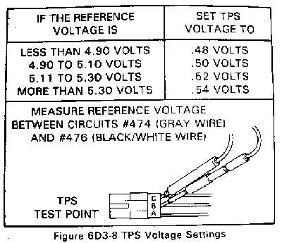
If the diagnostics are run after a Service Soon error is shown, and errors relating to the Throttle Position Sensor (TPS) and/or Idle Speed Control (ISC) are 21, 22, 26, 27and/or 30, it is likely that the TPS is worn. The TPS is a wirewound variable resistor, and when it is worn, it has the same effect on the Electronic Control Module (ECM) as a worn volume control on a radio. On a radio you will get a crackle when you adjust the volume......a worn TPS will give an intermittent throttle position readout to the ECM, and can cause the idle speed to fluctuate and cause the above errors. The TPS is used to send the throttle position to the ECM, indicating to the computer the angle of throttle. It senses 0-90 degrees of throttle angle. The ISC is controlled by the ECM and adjusts the idle speed dynamically according to load when the engine is at idle. The air conditioning compressor cycling or moving the gear selector from Park/Neutral to Forward and Reverse positions will change the load on the engine, which the ISC compensates for. If either the TPS or ISC are replaced, they need to be adjusted together. Instructions for adjusting them are covered HERE. Figure 6D3-8 is available HERE. |
Return to Main Page Comments? Corrections? Contact Webmaster Cory Heisterkamp 2022