ENGINE SWAP GUIDE - Part 3 of 3 ELECTRICAL
|
 Yeah...No. |
GENERAL BACKGROUND
One of the challenges of a 4100 swap-out is that some of the systems (Cruise, Warning Lights, Climate Control, etc.) are integrated into the ECM (aka ECU). Armed with the factory service lit and troubleshooting diagrams, as well as some real-world experience on these cars, I've put together some easy-to-follow solutions for each. Personally, I like to re-use as much factory wiring as I can, use solder and shrink tubing, and attempt to make the modifications look like it rolled off the assembly line that way. But, if you prefer a more 'quick and dirty' approach, there are some options for that as well.
Rule #1: Leave the ECM in place and connected. If you unplug it or remove it, you'll lose some climate control functionality. So just leave it be.
Rule #2: Don't hack up your 4100 Engine Harness....yet. If you followed the steps in Part 2, then it should all still be connected to your engine, and simply unplugged from the firewall. Details below....
Rule #3: You'd think 1982 through 1985 wiring would be the same, but there are differences (especially '82). When in doubt, consult the wiring diagrams at the bottom of this page for your particular model year.
ENGINE HARNESS HACKING
This doesn't have to be painful, and anyone can do it. Just take your time and double check your work. If you're running one of my E/K Display Units, then you can ignore some of the details below as it will drive your Coolant Temp Light directly, handle your torque converter and make your life easier in other ways.
The original HT4100 made use of an engine harness utilizing two firewall connectors. One is an round-ish, 8-sided “environmental" bulkhead connector on the center of the firewall and contains mostly low current, signal level I/O to sensors and actuators. The other is a square looking connector (immediately adjacent to the enviro conn) which contains more conventional circuits, like the alternator warning light, AC compressor wiring, starter solenoid wire, etc. Really, it's two halves that share a center mounting screw; one half for the engine, the other half for engine bay components.
The 4100 has a lot of wiring you probably don't need...off the top of my head, ISC, AIR solenoids, TPS wiring, Injectors, etc.
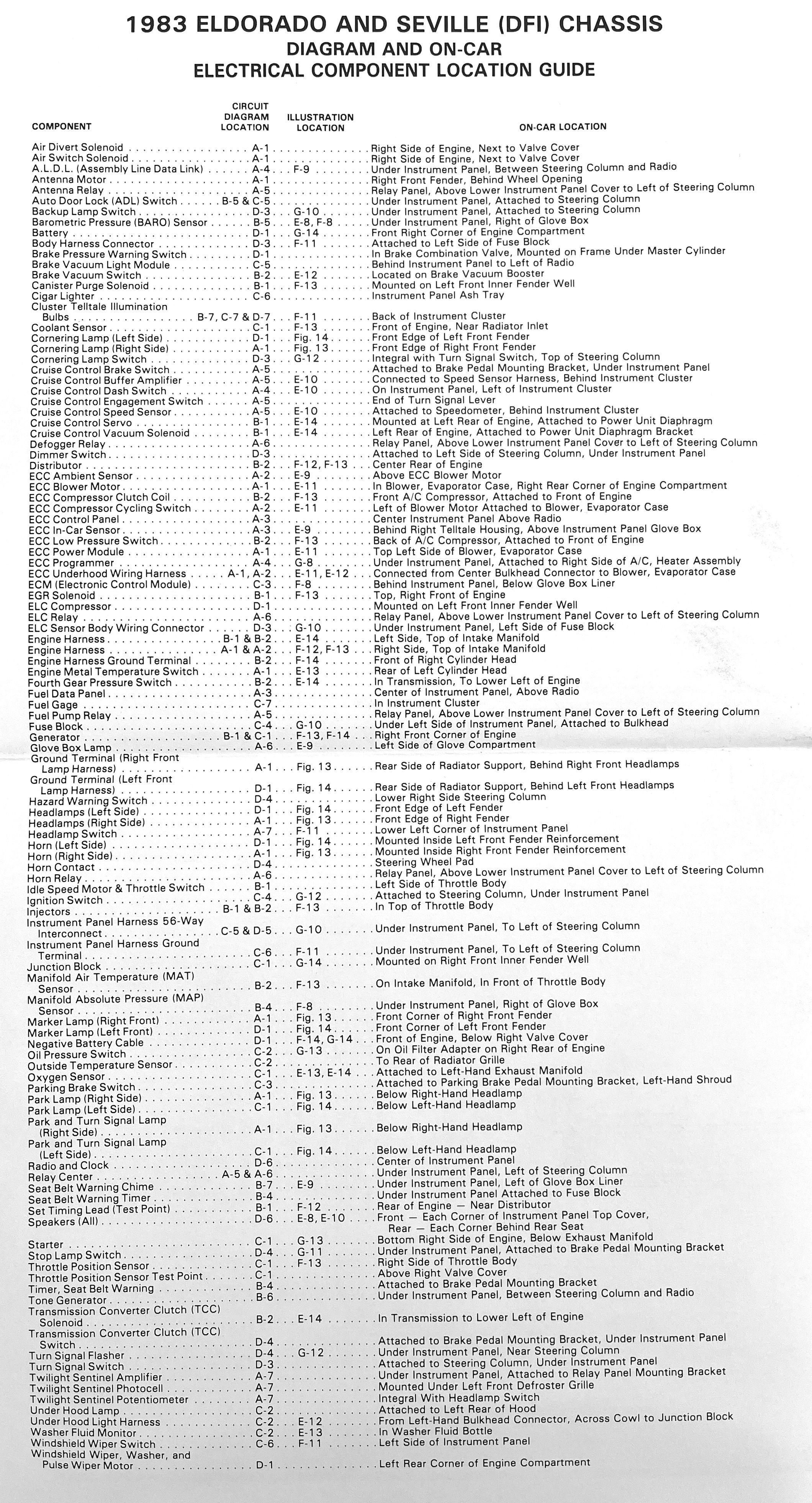
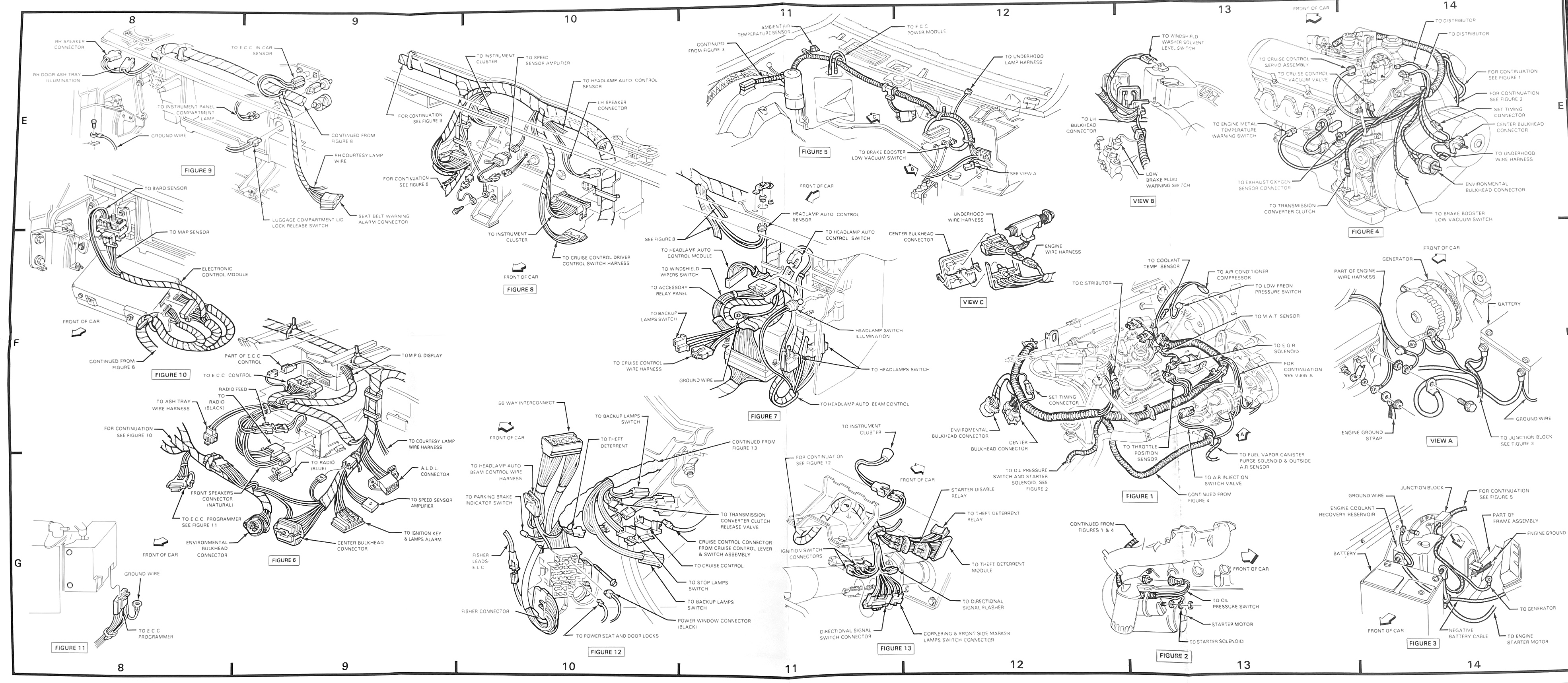
Grab a sharpie and some masking tape and mark the wiring you want to keep. Typically, this is: the 2-pin connector for the alternator, the connector for the A/C compressor, the wire with ring terminal that runs to the starter, the transmission connector, the heavy pink wire to the HEI distributor, the small green wire to the driver side for the Engine Metal Temp sensor, the very long wire pair that runs to the front driver side compartment for the external temp sensor, the 3 wire connector for the oil pressure sensor (this is tucked up above the oil filter on the passenger side). Also, keep the single wire that plugs into the hood light as well as the 2-pin connector that plugs into the brake booster (low vac). You can find further reference details at the end of this page, including diagrams that physically ID the engine components.
Some Tips:
- There are two pairs of wires that terminate in ring terminals and these are for ground purposes. Make sure they connect to a clean ground!
- On the 3-pin oil pressure connector, the tan wire is the one that triggers your Oil Pressure light. Keep this one. The two blue ones provide power to the fuel pump when oil pressure is present. Cut back/tape them if you don't need them.
- I like to leave the two cruise control connectors and the other long pair wire that went to the charcoal canister purge solenoid. These might cone in handy for future use.
- Follow back the two wires that went to the Coolant Temp Sensor (if not re-using this sensor)....trim them back about 6" from the firewall and solder a 470 ohm resistor across them (don't forget the heat shrink tubing). This will trick the computer into thinking the engine is up to temp, and your climate control fan will function without playing games. If you prefer, you can also do this at the ECU itself. See the Climate Control section below for more.
- The rest can be labeled and taped back. Only cut them off once you're sure you don't need them, and even then, it's prudent to leave one or two at full length (and buried in the harness tubing) in case you want to add something later. A perfect example is re-using the old MAT sensor wire to drive the Coolant temp light. Under hood, connect it to your new temp sending switch. At the ECU, snip it, and the wire that runs from the ECU to your coolant light, and connect them together. Presto, chango!
- Feel free to remove the convoluted tubing and cut the old tape to get all the wiring loose (after marking). The oil pressure wire, HEI+ wire, ground wires, alternator wires and MAT wire mentioned above will all reach their new destinations on the Olds motor without any lengthening or splicing. A little paint thinner on a shop rag will remove the sticky residue from the wire insulation.
- Since the alternator switched sides of the engine, you'll need to run a heavy gauge wire (8 or 6 ga) from the alternator B+ stud to the Battery + junction block on the passenger fender. You can either pay a bunch of money for new temperature rated wire and eyelets, or drop by the junkyard and pull one from something like a '93/94 GMT400 which is the perfect length and even includes a fusible link. You'll need to open the eyelet up just a little to fit the fender box stud.
 |
 |
 |
 |
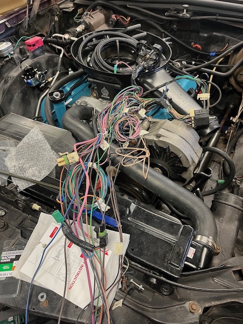
| 4100 Harness Stripped of Tape & Tubing |
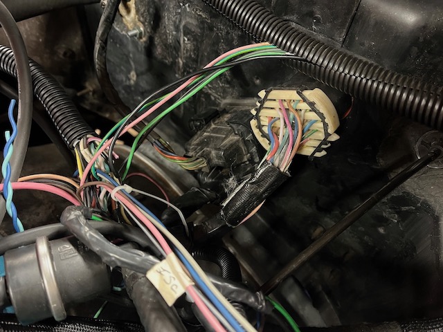
Bulkhead Connectors on Firewall; environmental connector on right. | Ground Eyelets now attached to front right of engine. Shrink-wrapped lead is aftermarket EFI. |
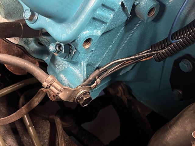
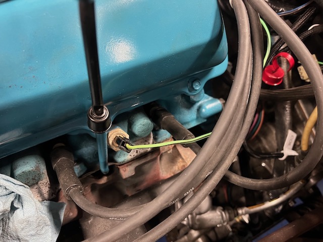
"Stop-Engine" Temp Switch |
|
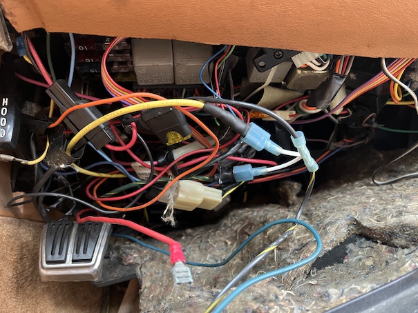
I highly recommend adding oil pressure and temp gauges so you can monitor your new engine, but retain the warning lights to grab your attention if needed. Decent quality gauges are expensive, and rarely look good |
 |
| Now might be a good time to ditch your digital speedometer for an analog unit. Not only do you gain a highly visible Coolant Temp light, but you won't spend eternity staring at a non-functional Fuel Range display, either. Conversion Details Here. |
- Oil Pressure Light:
The oil pressure switch on the 4100 has three terminals. One grounds out the light in the instrument cluster, the other two close a circuit that powers the fuel pump as long as oil pressure is present. We only care about the light ckt, so clip the Tan wire at the pressure switch and re-route this to your new oil pressure switch. On the Olds, this is typically at the top front of the engine just above and behind the waterpump. A switch from a carb'd Toro or Riv (without gauge package) will work fine and are cheap. If also running a pressure gauge, use a brass tee and pipe nipple to share this port. The other two unused wires can be clipped off anywhere it's convenient, preferably closer to the firewall as they still carry power, unless you're planning to reuse them for other purposes (like a gauge?). I like to stagger the cuts and tape ends to prevent shorting, and hide my cuts in the protective convoluted tubing for a cleaner look.
- No Charge / Batt Indicator:
You really don't need to do anything different here. This warning light is used as part of the alternator excitation circuit, which is standard for most GM charging systems. If you plug in the 2-pin flat-blade connector to your new alternator exactly like the original was (or just bolt the 4100's alternator in), this light will work correctly and your battery will charge properly. Even though the alternator has switched sides of the engine, the old wiring will reach if you cut the harness tape and re-route the leads.
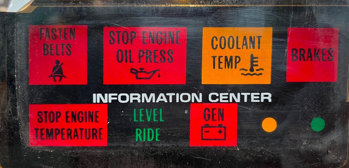
- Service Soon / Service Now Indicators:
You can either remove these two bulbs, or if it's easier, clip their leads at the ECM. These are cavities 4 & M on the Orange ECM Connector for '83-85. 1982 has only a single "Check Engine" bulb. Its circuit is Orange 10.
- Coolant Temperature Warning Light:
Even with an aftermarket temp gauge, there are good reasons for keeping your Coolant Temp light, especially with an analog dash where it'll grab your attention. Below are several options.
- The 4100's ECU not only used the engine block mounted temperature sensor to adjust fuel mixture and to delay turning on the Climate Control's fan until coolant is warm, it also drove the Coolant Temp light which would come on at 269F.
You could keep the 4100's temp sensor and wiring and screw it into an open coolant port; the ECU doesn't care what engine is sitting under that sensor, so long as it's connected. But it's important that temp sensors are in flowing coolant, which rules out the rear heater port location on an Olds intake. Plus 269F is a little hot for my liking.
- The preferable solution is to take a page from the Riv/Toro/Diesel/V6 cars. Mount a coolant temp switch on the engine (like a TS43T - 1/2" NPT), and wire this directly to your Coolant Temp light. When the switch sees an over-temp situation, it completes a ground to the engine block. The other side of the dash light already has switched 12V on it, and you can even re-use one of the (now spare) engine harness wires to connect to your switch (such as the old MAT wire example mentioned above). This can be accomplished right at the ECM by snipping the wire at Cavity K (83-85) or Cavity 12 (1982) in the orange connector: this wire leads directly to the Coolant Temp light and grounding it will cause it to light. Connect this to whatever wire you've selected that runs to your new temp switch and you're set.
And as Columbo says, just one more thing....If you'd like your Coolant Temp light to come on as a bulb check when cranking, the way it originally did, run a wire from position 35 of the ignition switch (this should be an empty terminal) to the side of the bulb you've connected the new temp switch to. When you turn the key, it grounds out 35 and your bulb should light.
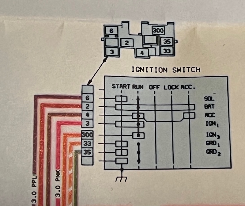 Use Ckt 35 for your bulb check. Should be empty on HT4100 vehicles, image above from diesel/V6 cars. Don't tap into an existing ground terminal or you'll backfeed your warning lights. |
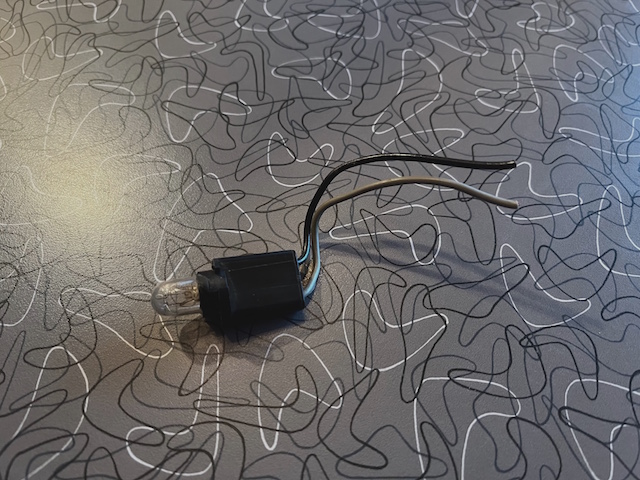 Pigtail & 194 bulb from Fuel Data backlight |
- I hesitate to even mention this...but if you'd rather not deal with any existing wiring, scavenge a bulb/pigtail from a spare Fuel Data backlight, provide one side with switched 12V, and run the other side to your new engine temp switch. It'll twist and lock right into the back of your speedometer housing where the old Coolant Temp lightbulb was, and is plastic-bodied so it's insulated from the speedo mylar circuit traces.
- Stop Engine – Temperature:
What the heck is this?! This light is driven by a metallic switch that threads into the block and closes at 320F! It also activates a warning chime, but lets face it, if this is going off, the 4100 is already a molten puddle of aluminum. You may have noticed that if the keys are in the ignition and the driver door is opened, this light illuminates. That's because they share the same warning chime. Maintaining this functionality is easy enough, just transfer the old thermal switch over to the Olds block; there are lots of threaded holes available in the side and rear of the driver side head. Plug in the existing green harness wire that went to the old one and you're good. (see pic above)
- If you're converting to a carb, DO remove the fuse and relay for the fuel pump circuit which are marked on the accessory fuse block under the driver side of the dash. DO remove the two 3 amp fuel injector fuses. The in-tank pump operates at around 14PSI and will flood your carb. A mechanical pump will pull through it just fine.
- If you're going to run low-pressure EFI, and the 14 PSI in-tank pump is sufficient, leave its fuse and relay in place. The ECU will command it to run for around 3 seconds at key-on, but you'll need a way to keep it running after the engine starts. The HT4100 used a 3-terminal oil pressure switch, and this should work fine screwed into an Olds. As mentioned above, the tan wire runs your oil pressure light. The two blue wires complete a circuit that provides 12V to the fuel pump, bypassing the relay whenever oil pressure is present. With those blue wires connected, all should work fine.
- If you're running high-pressure EFI, then whatever aftermarket controller you have is probably operating its own fuel pump relay and high pressure pump, but you may need the old in-tank pump to provide 'lift' for your new pump. I chose to snip the two wires feeding the coil of the factory relay, grounded one side (observe polarity..there's an internal snubber diode), and ran the other side to the new controller's Fuel Pump feed. Now each pump has its own relay and fuse, controlled by the new ECU.
- This can be as basic as a toggle switch you flip manually, a pushbutton and relay affair that you manually activate but that kicks out when tapping the brake pedal (or low vac), or as sophisticated as an aftermarket controller with delay. If you're using my E/K Display Unit, then this functionality is already built-in, just add an aftermarket vac switch. FOR DETAILS AND WIRING CLICK HERE.
- Don't let this intimidate you. Principal operation is quite simple: There's a vacuum operated servo "bellows" with two solenoids. One solenoid allows vacuum to pull in the servo, the other releases vacuum. The hardest part is figuring out where to attach the servo/bracket so it can pull on your throttle plate.
On the HT4100 cars, the ECM controlled the two solenoids, but it will no longer work if a Service Soon/Now light is on, and with a different engine under the hood, that's a guarantee. So what you need is the cruise control module from a V6 or Diesel Eldo/Seville. You plug your turn signal CC harness into the new module, provide it with speed from the (already existing) sensor on the back of your speedometer and "re-route" the needed circuits from the ECM to this new module.
The only trick is that not all modules work for all years. FOR DETAILS AND WIRING CLICK HERE.
Climate Control:
For interchangeability and "nuts and bolts", see the Tech Section
The Climate Control Head (panel with controls and display) does the heavy lifting in the system. It works with the blower module on the heater box to control blower speed, it works with the AC programmer under the passenger side dash to modify temp and direct air to where it needs to go, and it receives some key data from the ECM. (Technically, it receives all data on the data stream so it can also show diagnostics when asked.)
There are two pieces of data that are important for the climate control: 1. Outside Temperature. 2. Coolant Temperature.
Outside temp is obvious, and we left that connector and wiring in place so it should work fine, but why coolant temp? It's because the CC Head needs to know if the engine is warmed up or not before it switches on the blower when Heat is called for, so it's not blowing cold air on your feet.
Here are three options......
| Option | Impact |
| 1. Leave ECM in place & connected, and move the 4100's coolant temp sensor over to the new engine. |
Pro: All systems continue to work as designed (Outside Temp, Blower for Heat, Coolant Temp light). |
| 2. Leave ECM in place and connected, but don't bother with moving the coolant temp sensor/wiring. Just clip the wires. |
Pro: Outside Temp works. Neutral: Blower will work, but you have to tap the Defrost button first as an override to set things in motion. Con: Coolant Temp warning light no longer functions. See above for solutions. |
| 3. The Preferred Method: Clip the two temp sensor wires and solder a 470 ohm resistor between them. Either in the engine bay or at the ECM. |
Pro: ECM thinks the engine is warmed up, blower will function normally (though there's no "warmup delay"). |
Circuits & Such - This section is included as a general reference to support the activities above and to provide an overview of the entire electrical system.
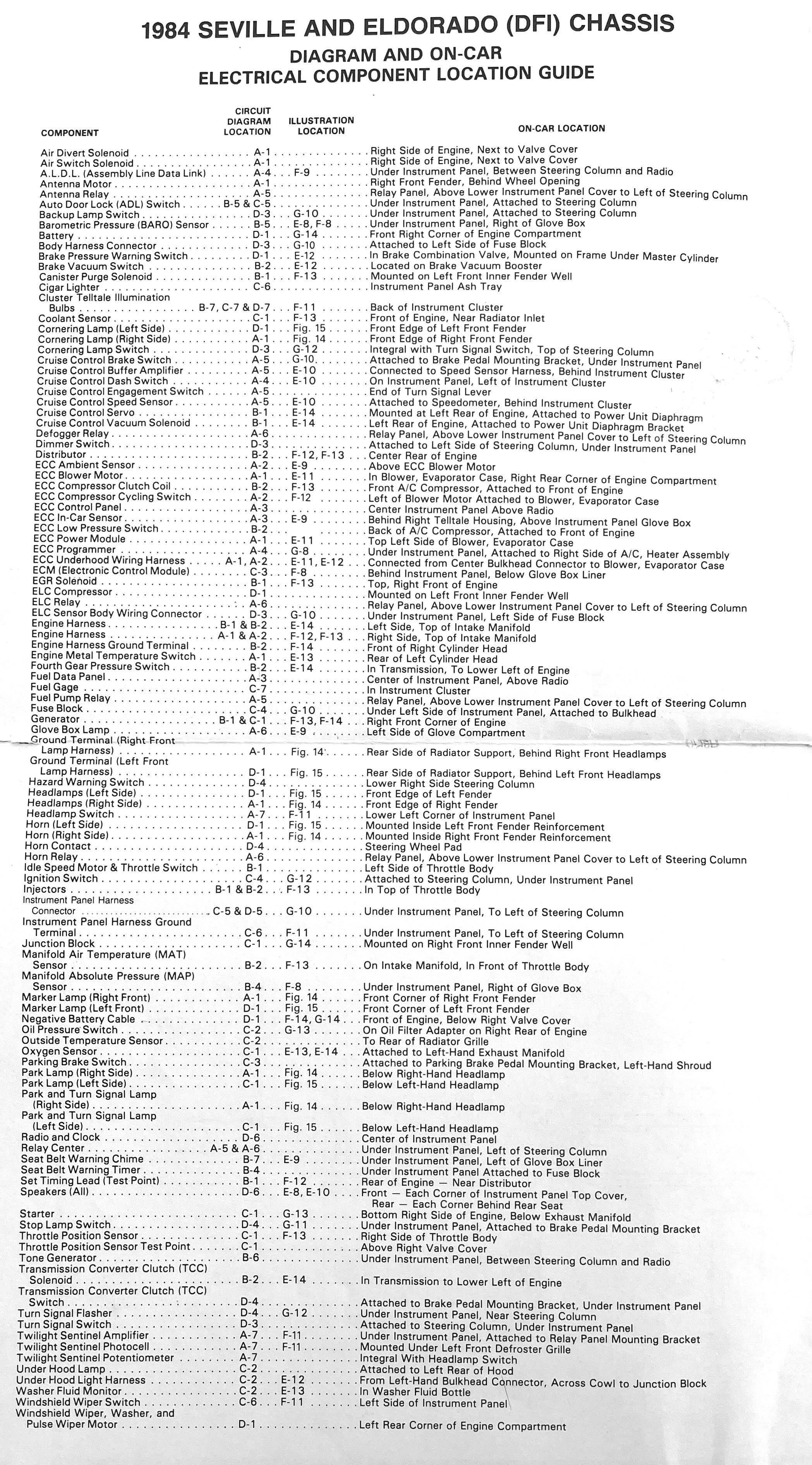
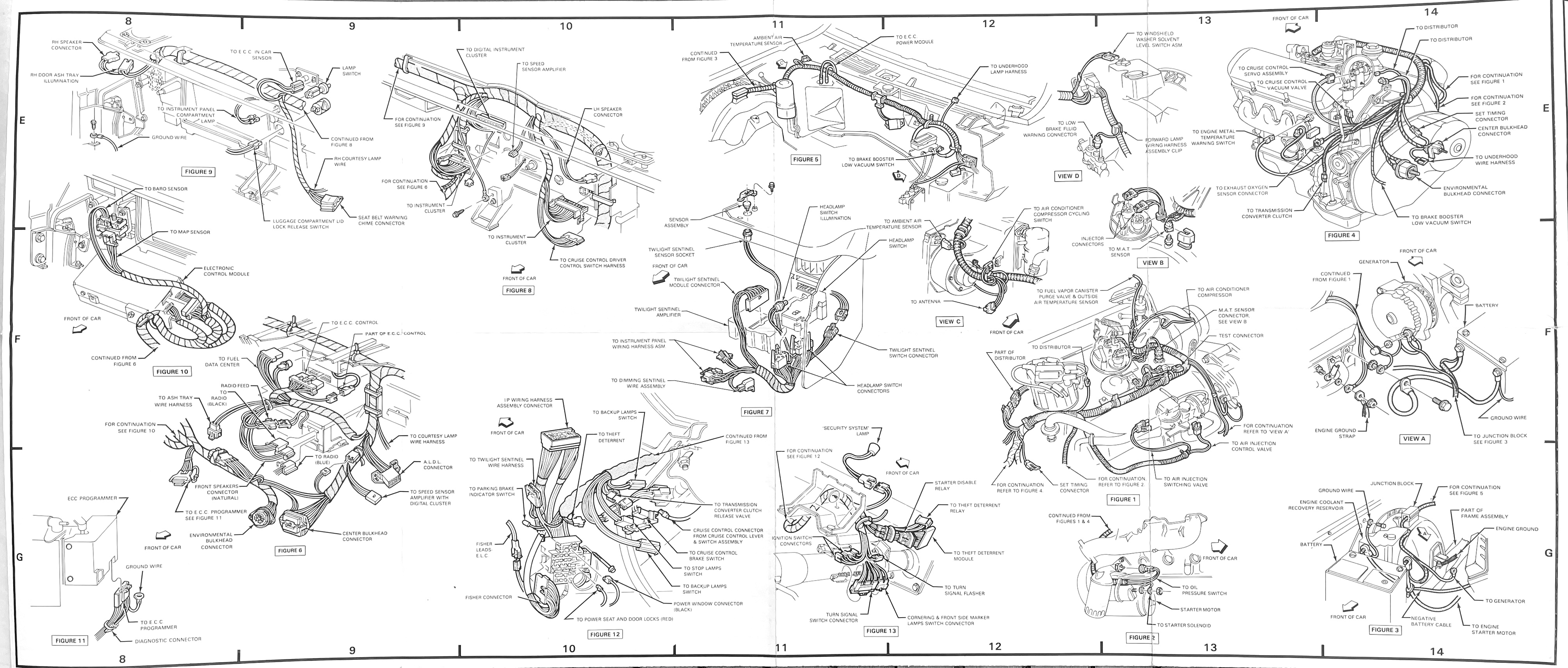
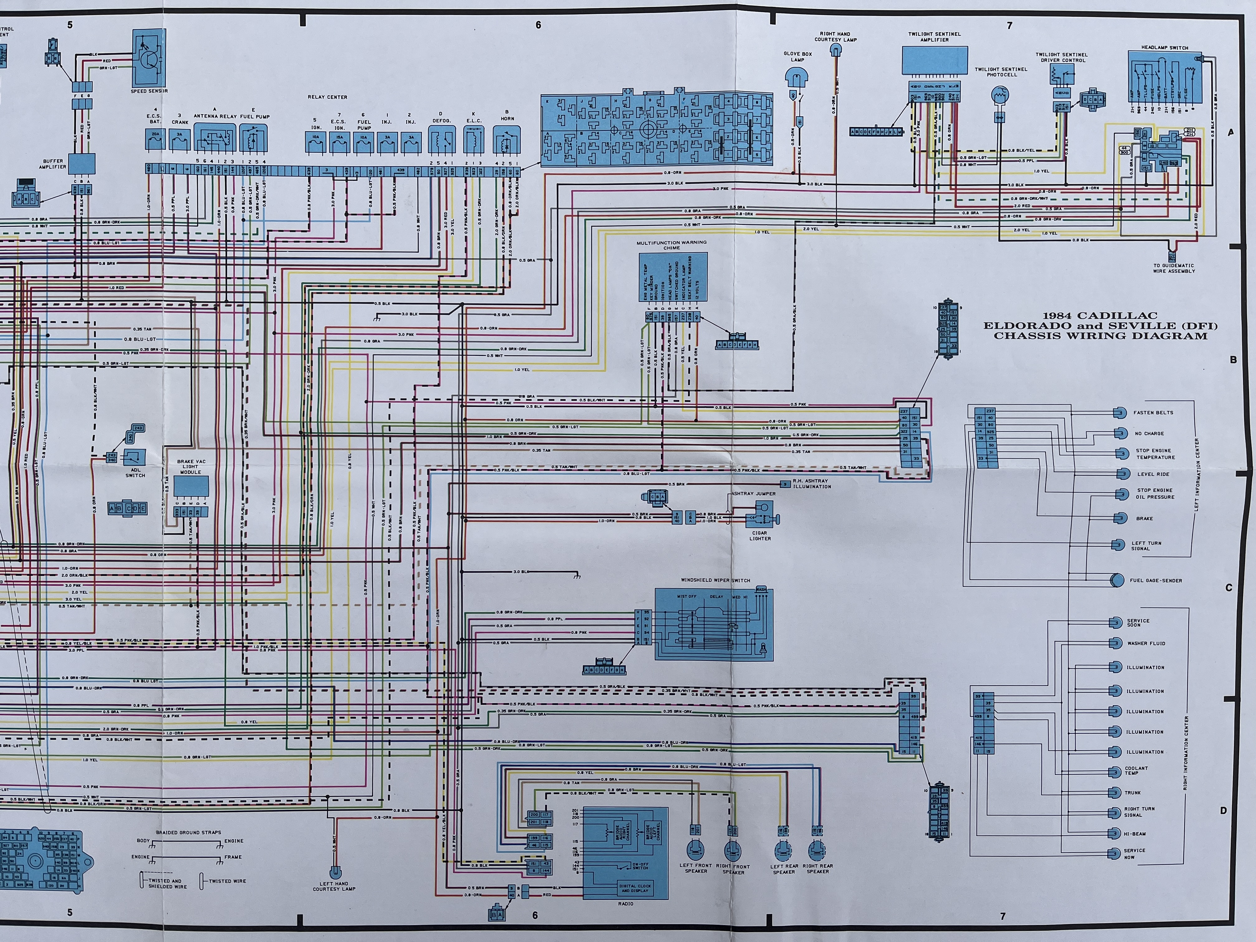
- 1984-1985 are 99.9% the same. There may be one or two wire color changes between the two years, but the circuit numbers and connector cavities are pretty much identical.
- 1983 laid the groundwork for 84/85. Circuit numbers and colors are very much the same as '84/85, the biggest difference is the rectangular firewall connector is a different style, with a different pinout. See below.
- 1982 is a different animal. It shares the same style firewall connector as '83, but the ECM wiring is different, and '82 still has a separate seat belt timer and buzzer, as well as a single "Check Engine" light.
Please be advised that wire colors may change year-to-year, and even during a production run. ALWAYS VERIFY BEFORE CUTTING.
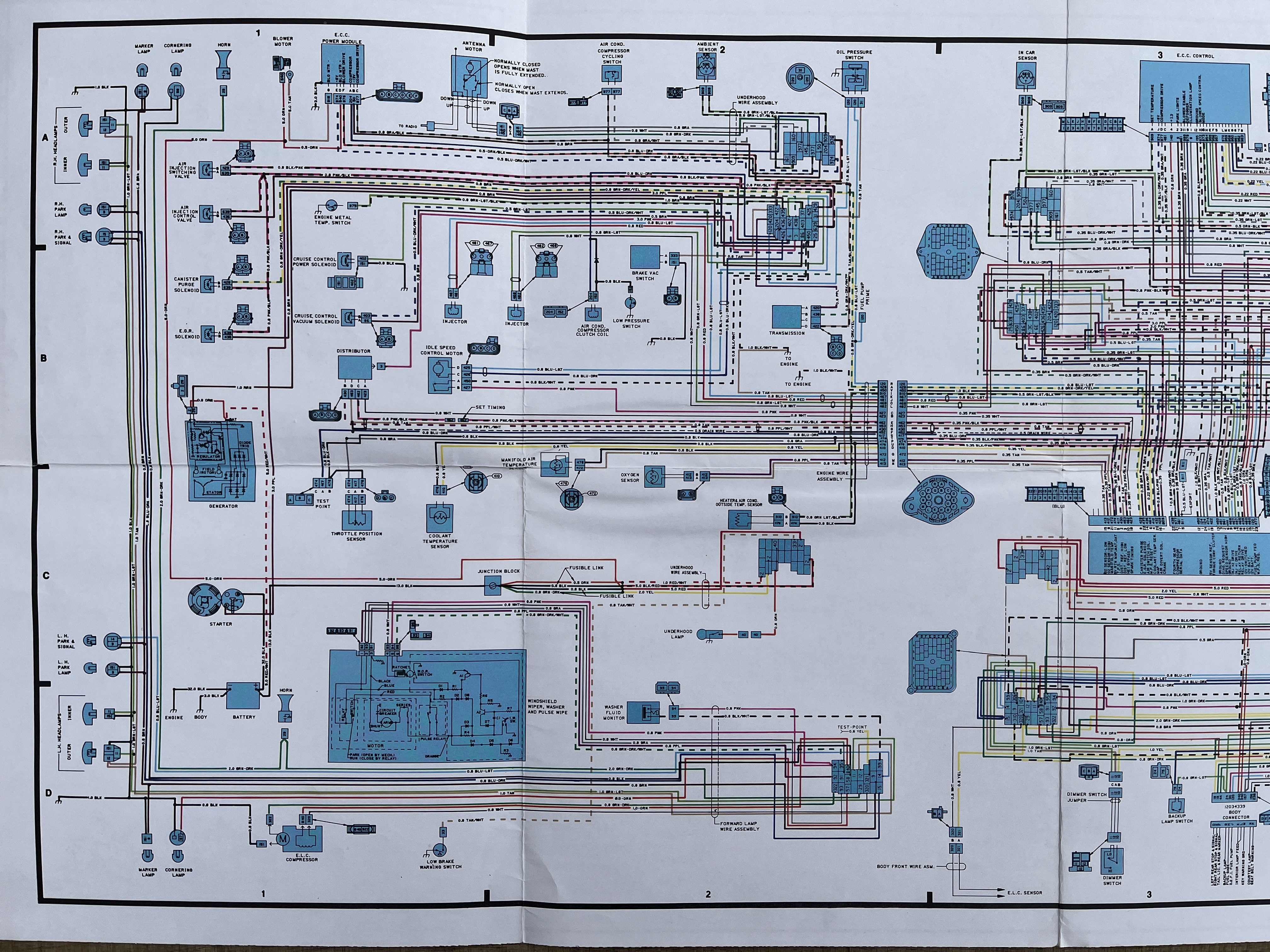
| Component Physical Locations - Click for Hi-Res | ||||||||||
|

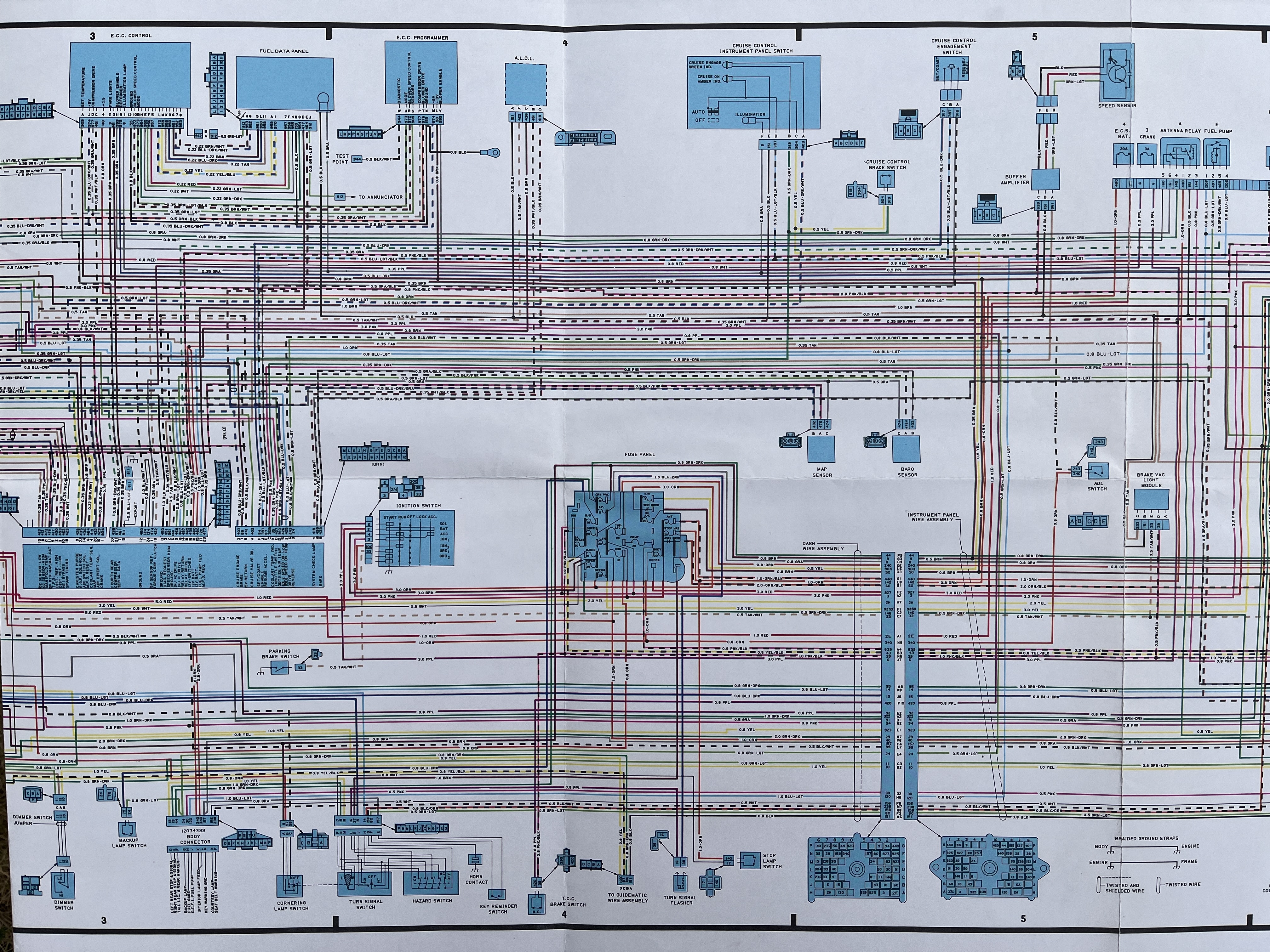
| E/K System Electrical Diagrams - Click for Hi-Res | ||||||||||||
|
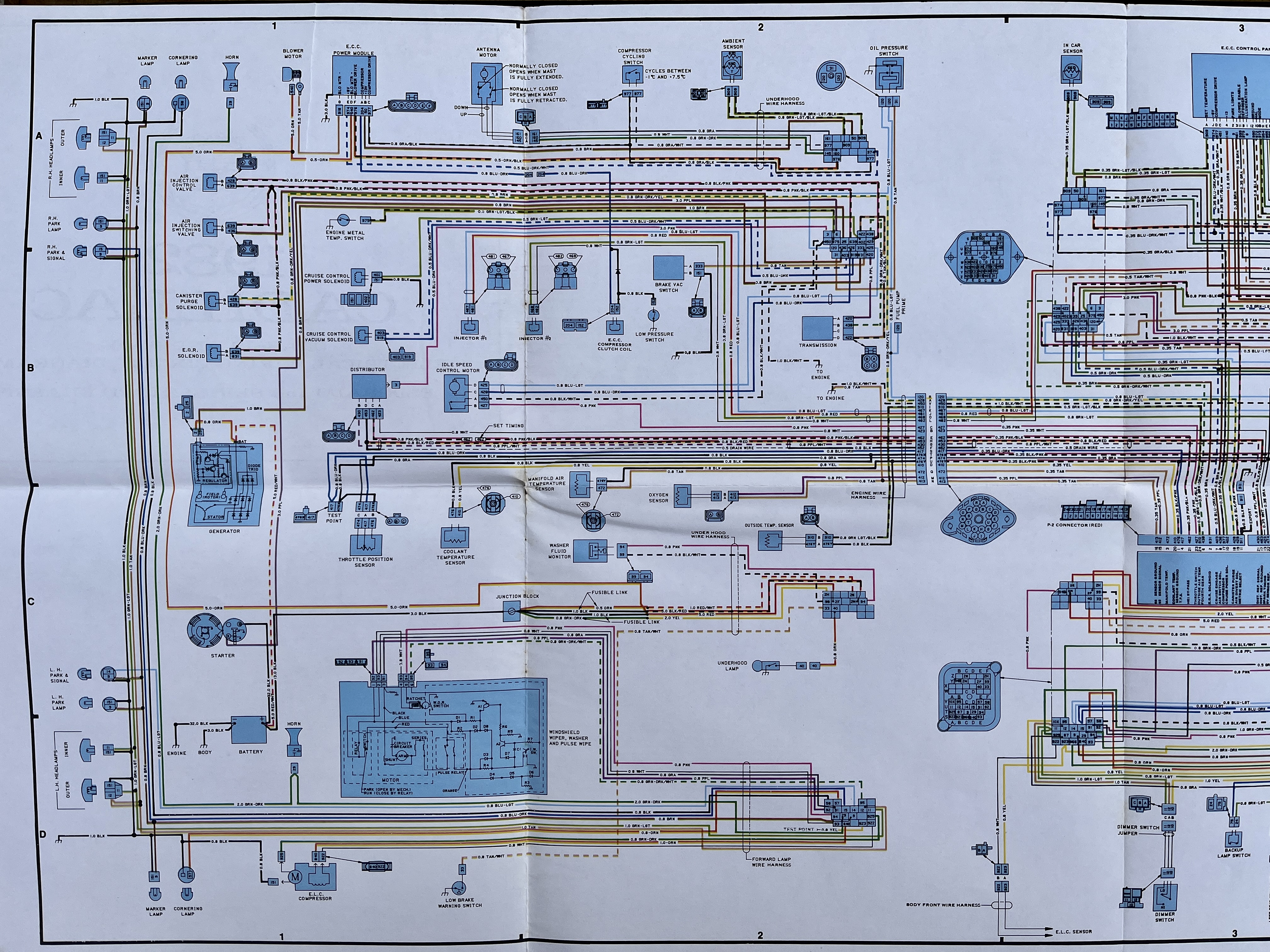
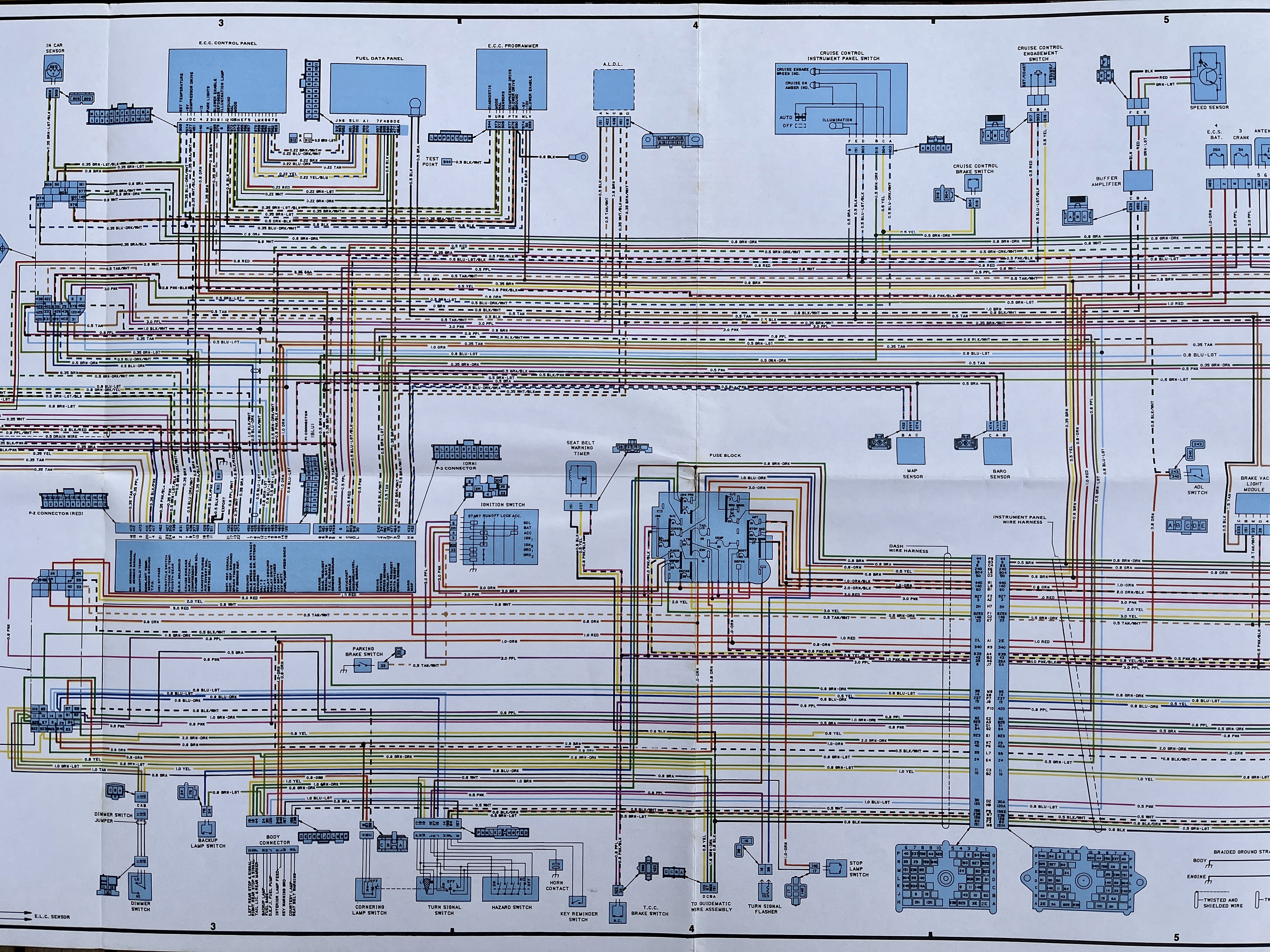
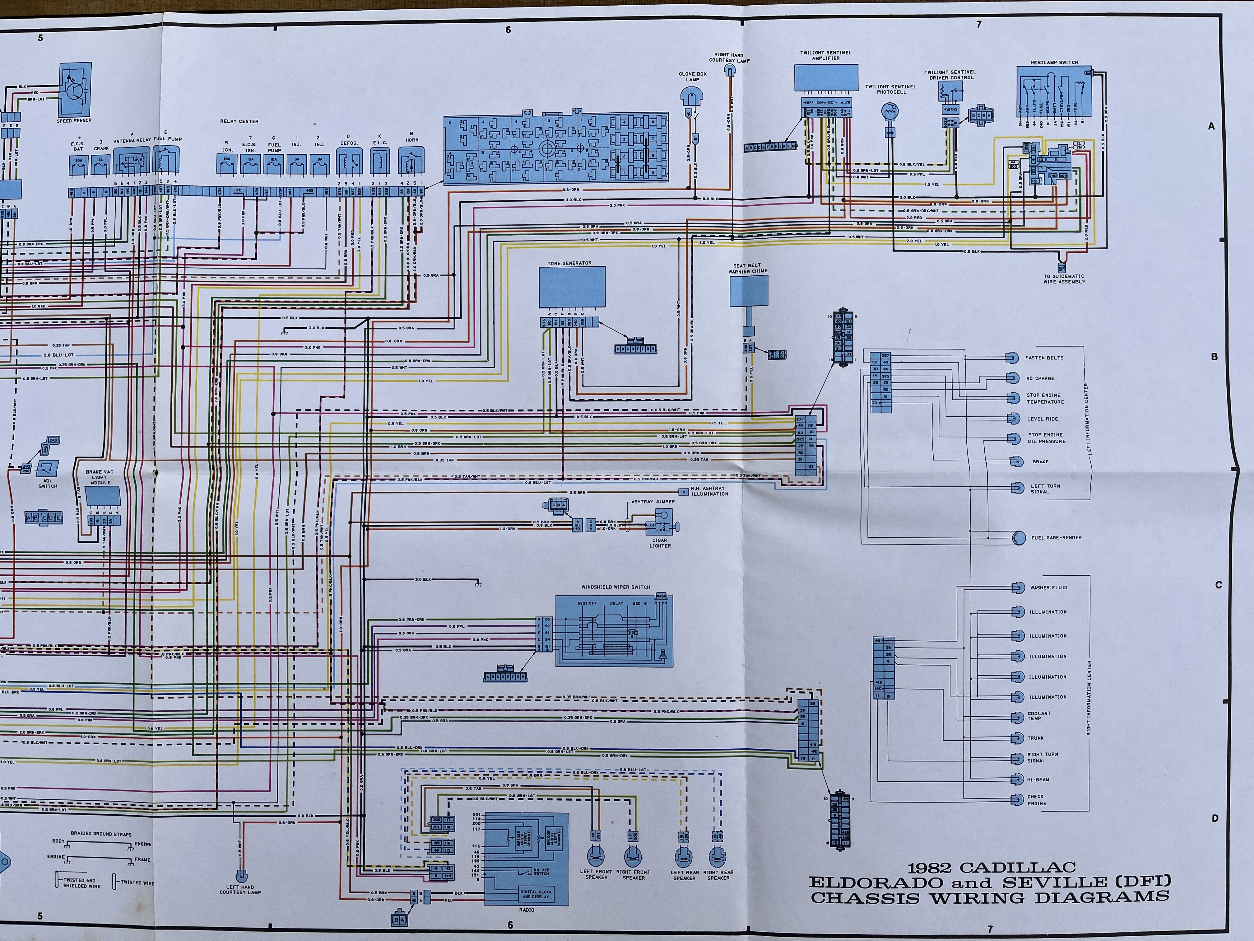
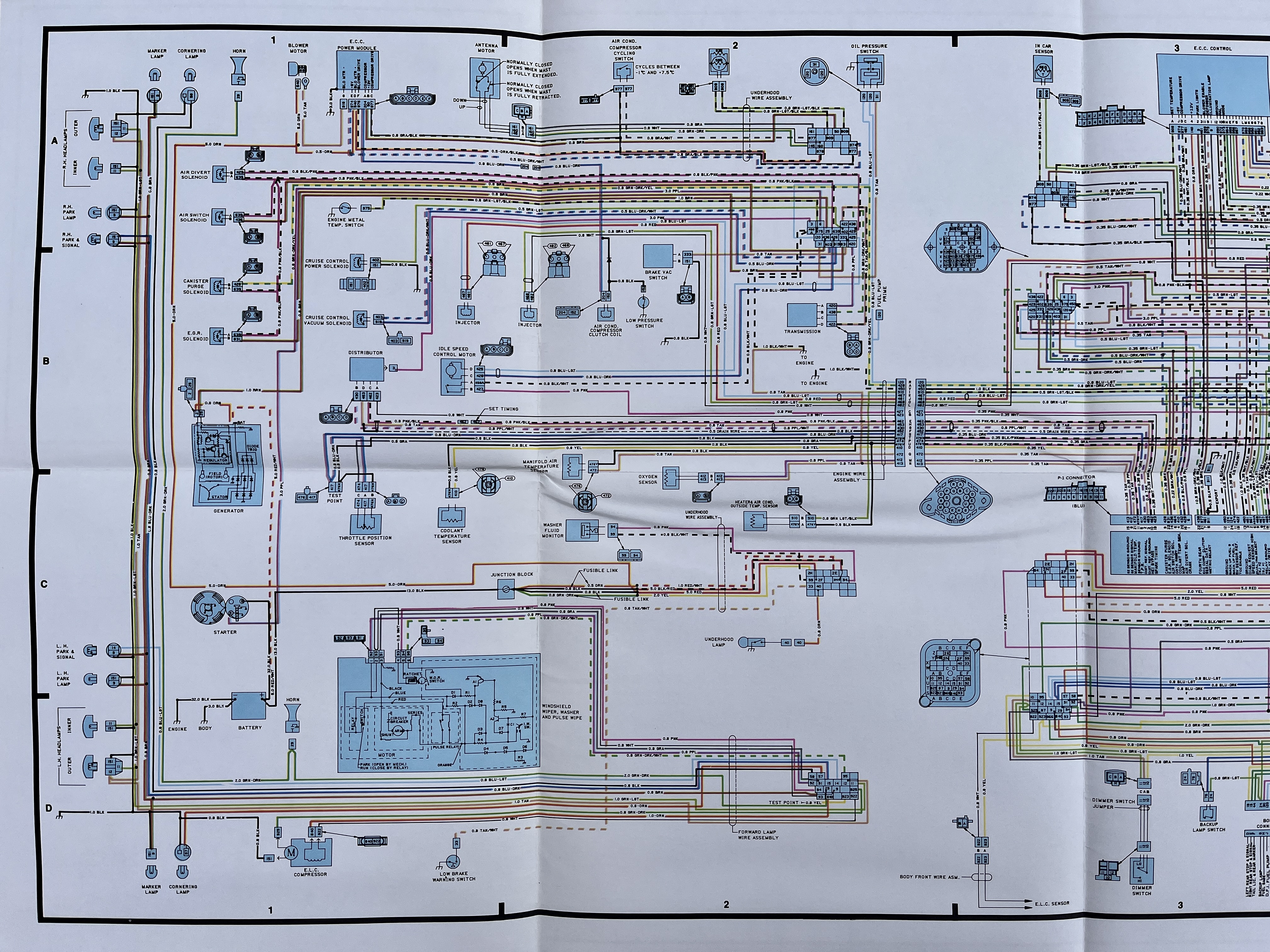

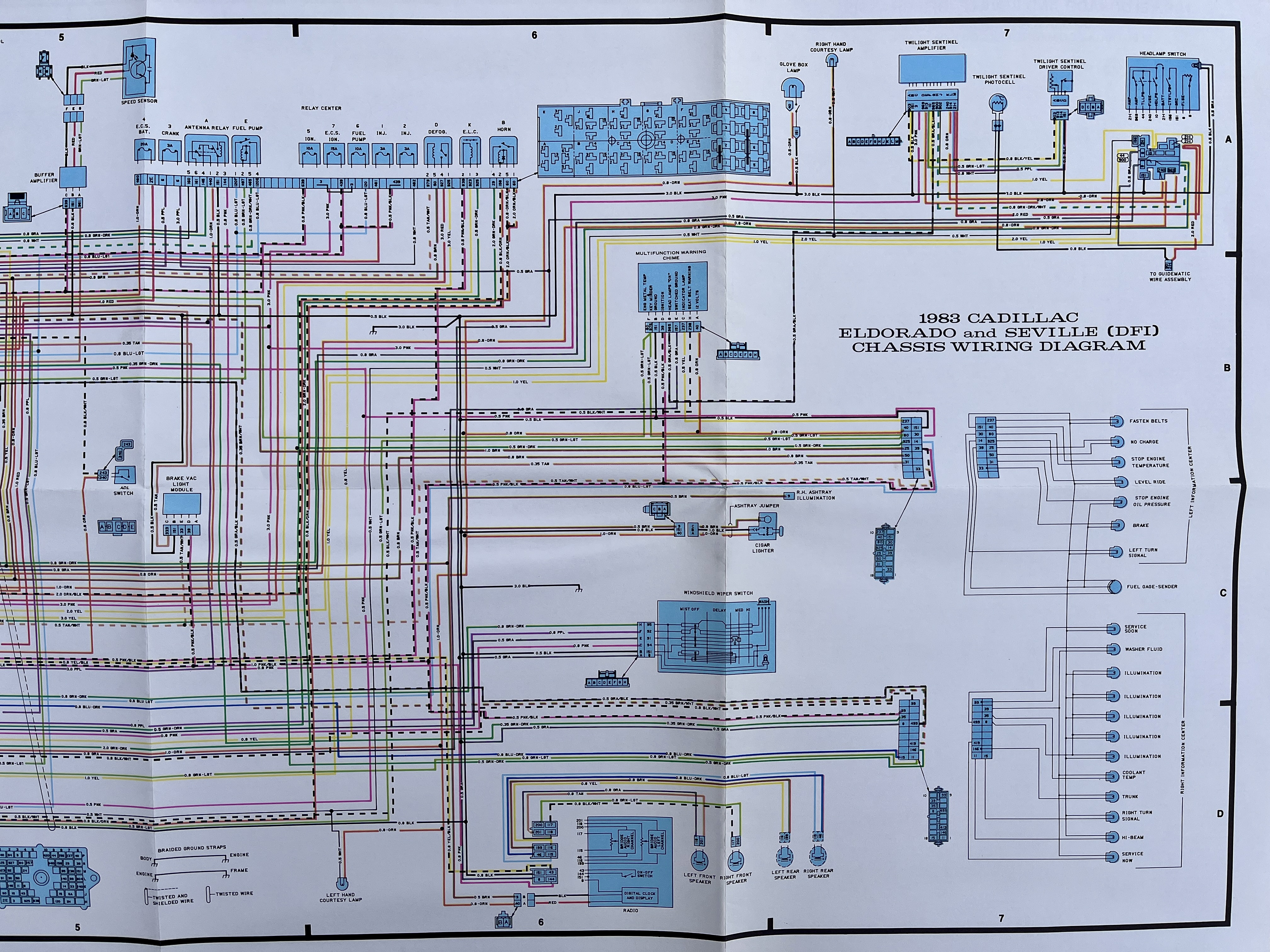
The Following is Verified for 1984/1985-Only. Double Check for '82 & '83.
|
On the Environmental Connector: Circuits No Longer Needed M – (ppl): O2 Sensor Q – (tan): Manifold Air Temp (MAT) P - (gray): TPS S – (drk blue): Test Point F (blk), G (Ppl/wht), H (tan), B (wht) - HEI Connector (for ECM timing) C – (pnk): ISC L (wht), O (lt grn), J (red), K (lt blue) - Injectors A (grn/yel): Canister Purge Valve (but may want to tuck back and retain) R (lt blue): Fuel Pump Prime Connector |
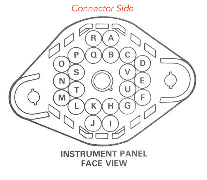 |
On the Environmental Connector: Circuits to KEEP
I (lt grn): Outside Temp Sensor, U (blk): Outside Temp Sensor Return
N (tan): Ground Eyelet (ground to engine)
D (yel): Coolant Temp Sensor, T (blk): Colant Temp Sensor Return
V (blk): Ground Eyelet (ground to engine)
|
|
On the Square Center Bulkhead Connector Half: Circuits No Longer Needed (see image & caveat below)
Note circuit numbers are given; see following chart to convert to terminal position
120 (lt blue): Oil Pressure switch signal for Fuel Pump
435 (brn): EGR
436 (brn) AIR Valve
426 (dk blue): ISC
425 (lt blue): ISC
429 (blk/pnk): AIR Valve
639 (pnk/blk): Common for AIR valves, Canister Purge, EGR
On the Center Bulkhead Connector Half: Circuits to KEEP (see image & caveat below)
333 (tan): Brake Low-Vacuum Switch
420 (ppl): Transmission Connector Ckt “A”, 422 (tan/blk): Transmission Connector Ckt “D”, 438 (dk grn/wht): Transmission Connector Ckt “B”
204 (dk blue): AC Clutch
402 (grn): Cruise Servo Power Solenoid (ground return is local to block)
403 (dk blue/wht): Cruise Servo Vac Solenoid, 86 (brn): Cruise Servo Vac Solenoid Return
6 (ppl): Starter Solenoid
3 (pnk): HEI 12V+
37 (lt grn/blk): Engine Metal Temp Switch (for warning light)
450 (blk/wht): 2 wires- one to ground eyelet which should be grounded to engine. Other to ISC: can clip this one out if desired.
31 (tan): Oil Pressure Warning Light
25 (brn): Alternator light (required for alternator to function)
|
The square center bulkhead connector terminals are arranged in an This image is from the '84 Electrical Guide and matches how my '85 is built. Below are the terminal positions relative to circuit numbers. 333: 6H |
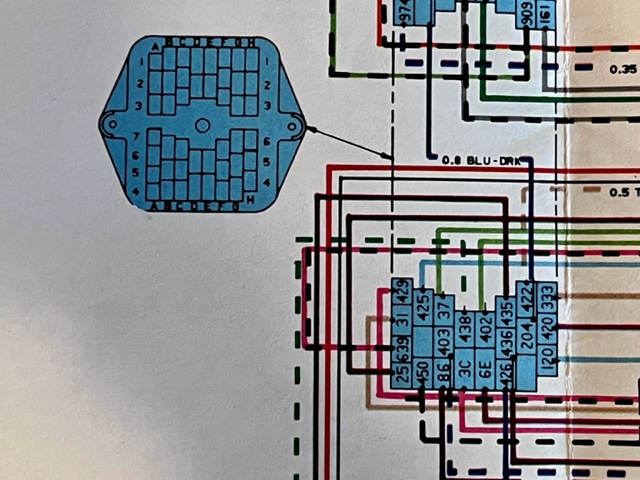 1984/1985 Center Bulkhead Connector - Emphasis on Lower Half |